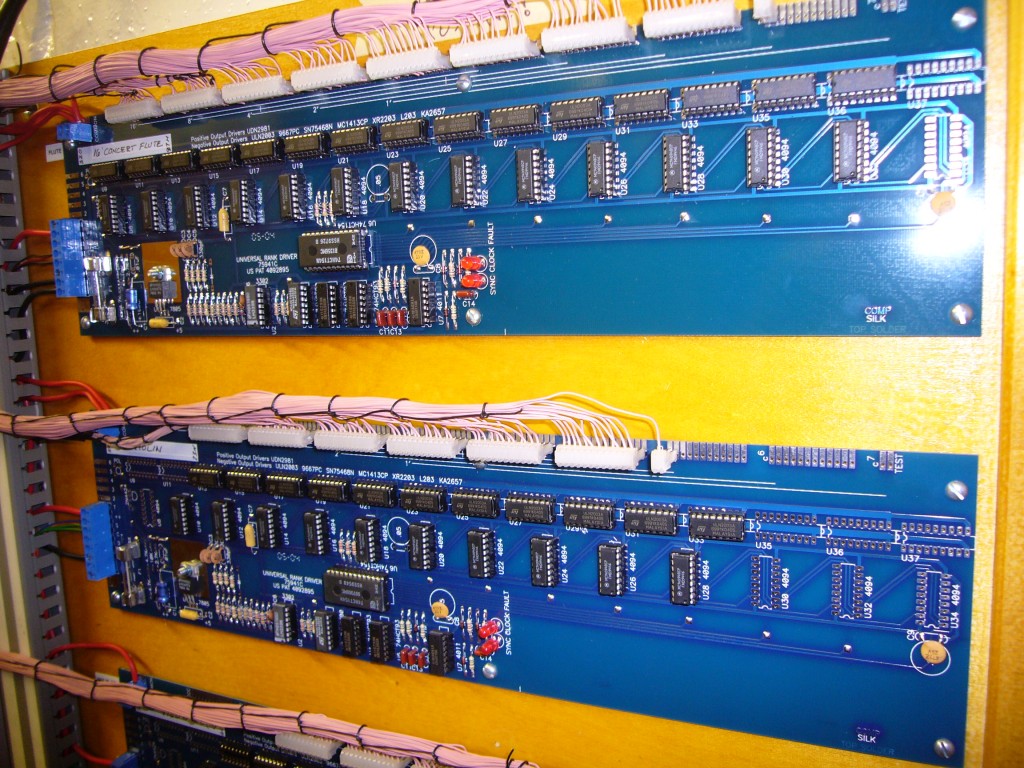
Electronic (or ‘solid state’) relays fall into three main categories according to the technology used. It is outside the scope of this site to provide a detailed description of how each works, but the following details explain the essential differences and features. Scanning and processor-based systems both offer significant advantages over traditional relays in terms of reduction in cost and complexity and improvement of flexibility.
Discrete component:
The logic function of the key-relay and stops witch of a traditional relay is replaced by diodes and transistor drivers. Although some reduction in complexity may be gained, especially by use of printed circuit boards, there remain many interconnections for each note of each stop. Modifications to such a relay system are (unless prepared for) difficult to do.
The main benefit of such systems is increased reliability through the elimination of electric or electro-pneumatic actions and the associated contacts. Their speed of response is virtually instantaneous.
Scanning (or Multiplex) relays
The key signals are combined into a time-based system, in which every key input of every manual (and pedal) is scanned at a given frequency to look for changes. The scanned output (key data) from each manual, carried by a single wire, goes through the coupler and pitch register functions to produce key data at any pitch (16′,8′, 4′ etc.) and is then combined with stopkey inputs to provide data for each rank of pipes, using a single wire per rank. Some systems combine this even further, going as far as a single cable to drive a complete instrument, although the practical benefits of this further integration of data are not always of value.The rank data is then decoded in the chamber to provide switched outputs for each action magnet of each pipe. The main advantage of such a system is the considerable reduction in wiring complexity. The specification of the instrument still has to be hard-wired, but modifications within reason can often be easily done. The scanning principle introduces a possible delay, but if the scanning rate is sufficiently high this is not normally found to be a disadvantage.
Well-designed systems of this type which use discrete integrated circuits (of CMOS and TTL design) are relatively easy to install and fault find (generally no more complex than a discrete component or traditional relay), and if well installed can be both robust and reliable. With the exception of the master oscillator and power supplies, these systems contain sufficient parallelism to prevent individual component failure from paralysing the instrument.
Processor-based relays:
Key and stop inputs are scanned using input cards, and action magnets for pipes and percussions driven by outputs driver cards. The input and output cards are usually connected by some kind of bus system (a common ring of wires running around the instrument, sometimes in the form of a ribbon cable), with some kind of processor (computer or dedicated unit) controlling the output cards in relation to the commands from the key and stop inputs. The comments about scan rate and responsiveness of scanning relays also apply to processor-based relays.
The function of inputs and stops is usually assigned by the computer/processor program, and on some systems the ability to re-program these by the user is a major selling point, simplifying wiring tasks and easing changes to the instrument and to the specification.
These systems also often include a combination action as well as the relay function.
Depending on the system architecture, these may be less robust compared to a conventional scanning relay

